
Maplin ROM Box: Difference between revisions
From CPCWiki - THE Amstrad CPC encyclopedia!
More actions
→Pictures: Added 300dpi scans of two Maplin Boards' PCB |
|||
| Line 22: | Line 22: | ||
Image:ROMBOX_04_MANUAL.JPG|ROM Box and photocopy of how-to build manual | Image:ROMBOX_04_MANUAL.JPG|ROM Box and photocopy of how-to build manual | ||
Image:ROMBOX_05_SCREEN.JPG|Connected showing ROMs | Image:ROMBOX_05_SCREEN.JPG|Connected showing ROMs | ||
Image:Maplin_ROMBoard_PCB_Top_(1).jpg|PCB Top (1) | |||
Image:Maplin_ROMBoard_PCB_Bottom_(1).jpg|PCB Bottom (1) | |||
Image:Maplin_ROMBoard_PCB_Top_(2).jpg|PCB Top (2) | |||
Image:Maplin_ROMBoard_PCB_Bottom_(2).jpg|PCB Bottom (2) | |||
</gallery> | </gallery> | ||
Revision as of 13:40, 1 November 2010

Description
The Amstrad Expansion System aka Maplin ROM Card from Maplin is a DIY project by Dave Goodman and John Attfield.
The Amstrad Expansion System (Part 1) is primarily a rom box for the CPC series, but had additional features:
- Special non-standard Buffered Expansion Port (with pre-decoded IOSEL line, on access to "free" I/O addresss)
- Lightpen socket (3.5mm stereo socket - just a connector with LPEN,5V,GND - without any additional electronics)
The Amstrad Expansion System (Part 2) adds some more features:
- 6x8bit I/O port (using two 8255 PPI chips)
- Additional power-supply module (PSU)
Pictures
-
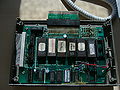 ROM Box with ROMs
 -
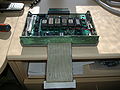 ROM Box
 -
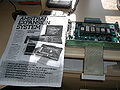 ROM Box and photocopy of how-to build manual
 -
 Connected showing ROMs
 -
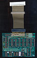 PCB Top (1)
 -
 PCB Bottom (1)
 -
 PCB Top (2)
 -
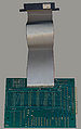 PCB Bottom (2)


.jpg)
.jpg)
.jpg)
.jpg)