Difference between revisions of "Schneiderware V/24 Interface"
| Line 20: | Line 20: | ||
|F9EEh || F9EAh || Schneiderware V/24 [[8253 chip]] Timer 2 (unused) | |F9EEh || F9EAh || Schneiderware V/24 [[8253 chip]] Timer 2 (unused) | ||
|- | |- | ||
| − | |F9EFh || F9EBh || Schneiderware V/24 [[8253 chip]] Timer Control | + | |F9EFh || F9EBh || Schneiderware V/24 [[8253 chip]] Timer Control |
|- | |- | ||
|} | |} | ||
| + | |||
| + | '''Caution''' - The '''clock source''' can be jumpered to 2MHz (default), or to 1MHz. Moreover, the '''handshaking''' signals (CTS/RTS, DTR/DSR) can be disabled via jumpers. There is no good reason for using the 1MHz setting, nor for disabling handshaking at hardware level - it's only "good" for provoking compatibility problems with software that expects the jumpers to be set to this or that position. | ||
== Pictures == | == Pictures == | ||
Revision as of 09:50, 30 September 2010
The Schneiderware V/24 Interface is a RS232 Interface, published by german magazine CPC Schneider International as part of their Schneiderware DIY series. The plain PCB, or the fully assembled board were also available via mail-order.
The ECB Bus connector of the board is intended to be plugged into the Schneiderware Basisplatine, but it could be also wired directly to the CPCs Expansion Port. The V/24 board additionally requires a Schneiderware Power Supply (or another external power supply with +12V/-12V).
- Schneiderware #3 V/24 (RS232 Interface) (8/1986 pages 70-77, plus correction from 9/1986 page 80)
I/O Ports
| Address (default) | Address (alternate) | Usage |
| F9E0h | F9E2h | Schneiderware V/24 8251 USART chip Data |
| F9E1h | F9E3h | Schneiderware V/24 8251 USART chip Control |
| F9ECh | F9E8h | Schneiderware V/24 8253 chip Timer 0 (TX clock) |
| F9EDh | F9E9h | Schneiderware V/24 8253 chip Timer 1 (RX clock) |
| F9EEh | F9EAh | Schneiderware V/24 8253 chip Timer 2 (unused) |
| F9EFh | F9EBh | Schneiderware V/24 8253 chip Timer Control |
Caution - The clock source can be jumpered to 2MHz (default), or to 1MHz. Moreover, the handshaking signals (CTS/RTS, DTR/DSR) can be disabled via jumpers. There is no good reason for using the 1MHz setting, nor for disabling handshaking at hardware level - it's only "good" for provoking compatibility problems with software that expects the jumpers to be set to this or that position.
Pictures
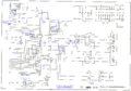
V/24 Schematic
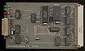
V/24 (component side)
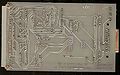
V/24 (solder side)

.jpg)
.jpg)