Plus Vectored Interrupt Bug
Plus Vectored Interrupts
On the Amstrad Plus and GX4000 it is possible to use Z80 Interrupt mode 2 (IM 2). When maskable interrupts are enabled (EI) and the interrupt is acknowledged by the Z80, the ASIC will provide a vector which is put onto the bus.
This vector and Z80 register I are used to form an address:
(I*256)+vector
The Z80 will then read a 2-byte address which is the location of the interrupt handler.
Bit 0 of the vector will be 0. Bits 3..1 are generated by the ASIC based on the interrupt source (one of the DMA channels or raster interrupt). Bits 7..4 are defined by writing a value to the ASIC IVR register (at &6805 in the ASIC registers).
The raster interrupt interrupt comes from the CPC compatible 52-line interrupt OR the Plus programmable line interrupt (PRI at &6800 in the ASIC registers).
Bit 0 of IVR is set to 1 at power-on but the other bits are undefined, so you should either:
- Set the IVR value by writing to 6805 after unlocking the asic and making the registers visible
e.g.
...
di
call asic_unlock
ld bc,&7fb8
out (c),c
ld a,1
ld (&6805),a
ld a,&40
ld i,a
ld hl,dma0_handler
ld (&4000),hl
ld hl,dma1_handler
ld (&4002),hl
ld hl,dma2_handler
ld (&4006),hl
ld hl,raster_handler
ld (&4008),hl
im 2
ei
...
- OR, you can repeat the same interrupt function handlers through the entire 256 byte vector range.
e.g.
...
di
ld a,&40
ld i,a
ld hl,dma0_handler
ld (&4000),hl
ld hl,dma1_handler
ld (&4002),hl
ld hl,dma2_handler
ld (&4006),hl
ld hl,raster_handler
ld (&4008),hl
ld hl,&4000
ld de,&400a
ld bc,256-&a
ldir
im 2
ei
...
See Arnold_V_Specs_Revised for more information.
The Vectored Interrupt Bug
The Vectored interrupts are bugged. Amstrad knew about this and removed information about the IVR register and vectored interrupt from later ASIC specification documents.
Following discussions on cpcwiki involving roudoudou, Longshot, gerald, arnoldemu and dragon the cause of the bug has been identified, through testing and from analysis by gerald with his logic analyzer and a workaround has been identified.
The bug relates to the raster interrupt. When a raster interrupt is acknowledged sometimes the vector will be 6 (for raster interrupt) or 4 (for dma channel 0 - the lowest priority interrupt).
- If the instruction at the time of interrupt acknowledge is located in a memory region where A13=0 then the bug happens. The bug is not dependent on RAM or ROM or I register value. The location of the instruction is important. The bug also doesn't seem to happen when the instruction is purely based on opcode read operation (e.g. single byte opcodes that don't read/write memory).
- If the instruction at the time of interrupt acknowledge is located in a memory region where A13=1 then the bug doesn't happen. Therefore to workaround the issue put your code between &2000-&3fff, &6000-&7fff, &a000-&bfff, &e000-&ffff. You can place your I value anywhere and the code for your interrupt handlers can
be anywhere.
Technical
The bug is related to logic around link LK106 and IC IC116 near the Z80 which relates to the Z80 signals /IORQ, /RESET, A13 and /WAIT, but the exact reason this logic is here is not known.
See 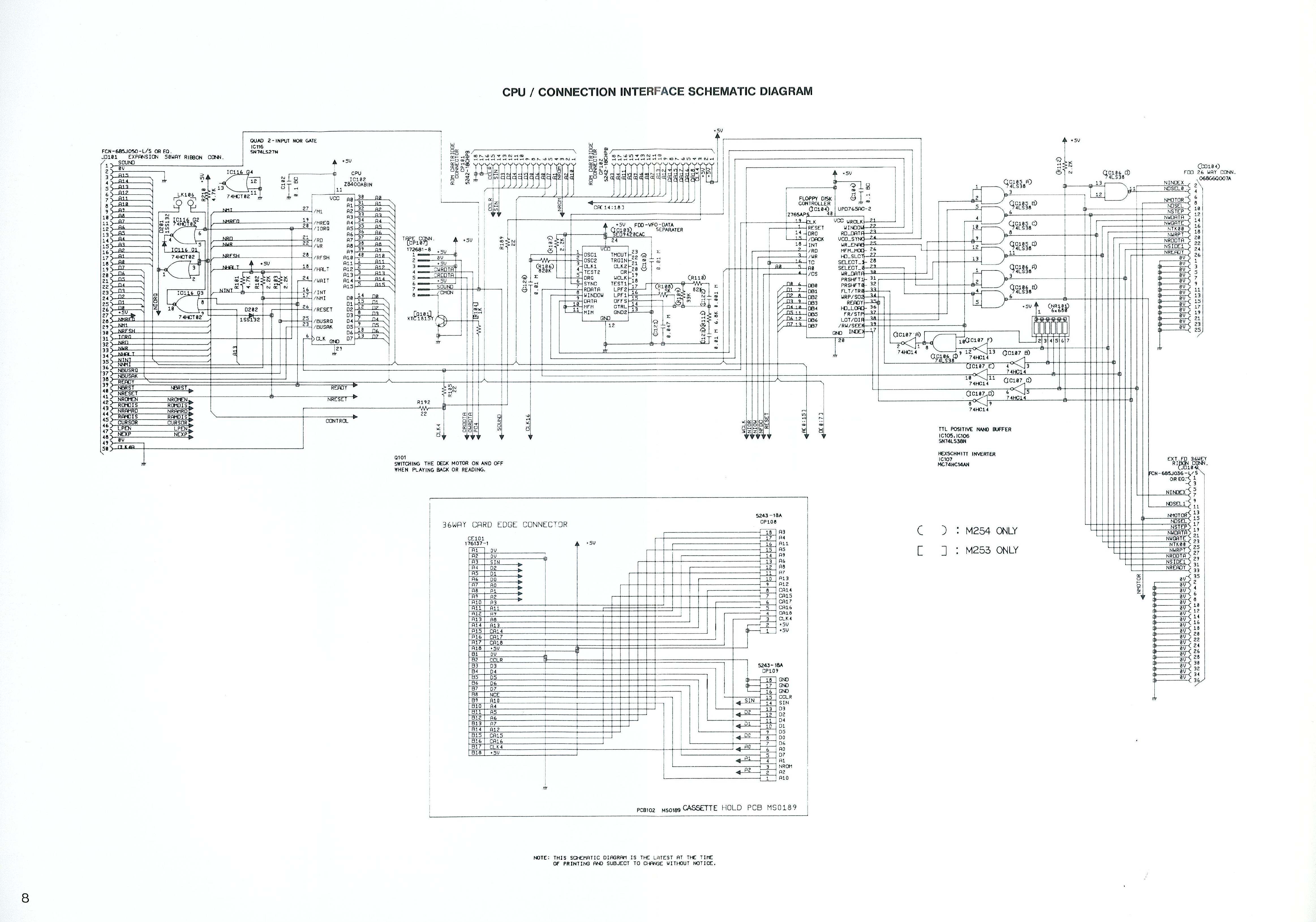
Logic analysis:
http://www.cpcwiki.eu/index.php/File:IM2_Plus_Ack_Bug.png
When a raster interrupt is pending it has been found that the ASIC sees two interrupt acknowledge from the Z80.
With the first, it will auto-clear the raster interrupt, record the information in the DCSR register and output the raster interrupt vector onto the bus.
When it sees the second, because the raster interrupt has been seen and no DMA interrupts are pending, it defaults to the the vector for DMA channel 0.
The logic around the Z80 shortens or lengthens the IORQ based on A13 and that is why the bug doesn't happen when A13=1.