Difference between revisions of "Fischertechnik Interface"
(→Pictures) |
|||
| Line 33: | Line 33: | ||
<gallery> | <gallery> | ||
Image:Fischertechnik Scheider Interface.JPG|Schneider Interface (20pin cable with 34pin connector) | Image:Fischertechnik Scheider Interface.JPG|Schneider Interface (20pin cable with 34pin connector) | ||
| + | Image:Fischertechnik-C64-Interface.JPG|Commodore Interface (10pin cable with 24pin connector) | ||
Image:Fischertechnik Interface Adapter IBM Amiga Atari 25pol.jpg|right|thumb|20pin-to-25pin PC Adapter]] | Image:Fischertechnik Interface Adapter IBM Amiga Atari 25pol.jpg|right|thumb|20pin-to-25pin PC Adapter]] | ||
</gallery> | </gallery> | ||
Revision as of 09:14, 7 April 2010
The Fischertechnik Interface is used for the Fischertechnik Trainingsrobot and for the Fischertechnik Computing Experimental kit.
Inputs/Outputs
The interface for the CPC (as well as newer RS232/USB versions) consists of:
- 8 single bit inputs ports (eg. for sensing when a robot-arm reached its end-position)
- 4 "bidirectional" ports (for motor control) (here "bidirectional" rather means "three-state-output" aka "forward/stop/backward")
- 2 analog inputs (eg. for temperature sensor)
Technical
Fischertechnik has built several interfaces:
- Interface for Commodore 24pin User Port (used on C64/VIC20)
- Interface for one-directional 25pin printer port (used on PCs) (this might have been also used by CPC...? if so, with 34pin/36pin connector, of course)
- Interface for RS232 port (used on PCs) (9600 baud, 8bit, no parity, 1 stopbit)
- Interface for USB port (used on PCs)
Parallel Printer Port Interface
Designed for one-directional printer ports: Data is read/sent via Pin11/Pin4 (which data is to be transferred is selected via the other DATA lines) (details on how the data is transferred exactly are unknown?).
Printer Pin        Interface Signal    Comment
Pin2 (Data Bit0)   Load-out            ;motor control output
Pin3 (Data Bit1)   Load-in             ;digital sensor 8bit input
Pin4 (Data Bit2)   Data-out            ;data from computer
Pin5 (Data Bit3)   Clock               ;data clock
Pin6 (Data Bit4)   Trigger-x           ;analog sensor X input
Pin7 (Data Bit5)   Trigger-y           ;analog sensor Y input
Pin11 (Busy)       Data-in             ;data to computer
The parallel fischertechnik interface has a 20pin cable. The supported computers have different pin-outs: 25pin DSUB (PC/Amiga/Atari), 34pin Edge (CPC464/CPC664), or 36pin Centronics (german CPC6128). To solve that, some cables have a N-pin connector on a 20-pin cable. Others have a 20-pin connector, with additional 20-pin to N-pin adaptor.
Pictures
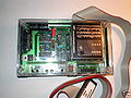
Schneider Interface (20pin cable with 34pin connector)
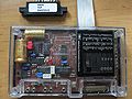
Commodore Interface (10pin cable with 24pin connector)
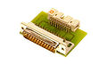
right|thumb|20pin-to-25pin PC Adapter]]


