Dobbertin Smart Watch
The Dobbertin Smart Watch was produced by Dobbertin Industrie Elektronik, a German company. This real time clock was relative wide spread in the 80ies and 90ies.
Contents
Technicals
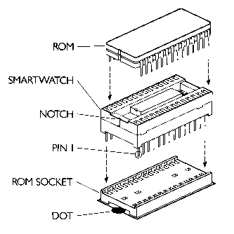
The Smart Watch consists out of the RTC itself and an EPROM expansion with a lot of RSX commends. The RTC itself was inserted like an EPROM in any kind of ROM or EPROM card. Further it contains a little battery. At least one clock is still running in 2010!
Dallas Semiconductors Smart Watch
Forward: Whether or not the Dobbertin Smart Watch does actually contain chipset from Dallas Semiconductors is still unknown... The term "Smart Watch" and the technique of inserting the RTC into a ROM socket does indicate that the Dobbertin RTC has some relation to the Dallas product... It might be exactly that hardware, or similar compatible or incompatible hardware, or something entirely different... can somebody verify which chip(s) are used in the Dobbertin RTC ?
The 28pin Smart Watch (DS1216) is an adapter that can inserted in standard ROM sockets, a ROM chip can be mounted on the adapter, finally, inside of the adapter is a 16pin Phantom Time Chip (DS1315). Normal memory reads are forwarded to the piggyback ROM. After reading from a specific sequence of addresses, the ROM is disabled, and data is instead read from the Phantom Chip via 1bit databus. Writing to the Phantom Chip is done by reading from a specific sequence of addresses, too.
- Media:DS1216-smart-watch.pdf - Dallas Datasheet for 28pin Smart Watch Adapter
- Media:DS1315-phantom-time-chip.pdf - Dallas Datasheet for 16pin Phantom Time Chip
- Media:DS1216-app-note-52.pdf - Dallas Application Note on Smart Watch and Phantom Time Chip
64bit packets
Accessing the RTC is done by following steps
- Read 1 or more bits (this resets the recognition pattern; best read at least 64 bits, in case the chip was in the 64-bit data read phase)
- Write the 8-byte (64bit) recognition pattern
- Read or Write the 8-byte (64bit) register data
The 8-byte (64bit) pattern/data is transferred serially, LSB first. The used bits on address and databus are:
A2 data direction (0=write, 1=read)
A0 data written to RTC, when A2=0=write
D0 data read from RTC, when A2=1=read, and only when pattern recognized
Recognition Pattern
The recognition pattern is: C5h,3Ah,A3h,5Ch,C5h,3Ah,A3h,5Ch.
Register 0..7
0  1/100 Seconds (BCD 00h..99h)
1  Seconds       (BCD 00h..59h) (Bit7=Zero)
2  Minutes       (BCD 00h..59h) (Bit7=Zero)
3  Hours         (BCD 01h..12h or 00h..23h) (Bit5=PM when Bit7=12-hour mode) (Bit6=Zero)
4  Day of Week   (01h..07h) (Bit4=Disable Reset input, Bit5=Disable OSC, stop clock) (Bit3,6,7=Zero)
5  Day           (BCD 01h..31h) (Bit6-7=Zero)
6  Month         (BCD 01h..12h) (Bit5-7=Zero)
7  Year          (BCD 00h..99h)
Pictures
Downloads
- (EPROM with RSX commands) - none such...?
- (disc with CP/M driver) - none such...?
Software
- The TimeROM+ Software provides RSX commands to use the RTC under BASIC.
- Support for CP/M Plus was provided. The TIMEROM+.COM program sets the software clock according to the RTC.
- The Smart Watch is also supported by FutureOS.
Source Code
(Have to find out how to implement it here... please be patient)

